Vehicle
In this tab, the user will be able to design his vehicle. There are five main items.
Sommaire
Mass properties
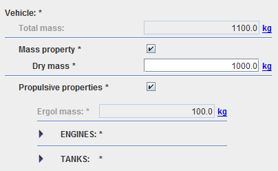
This item is very simple as the user has only to enter the dry mass value (for ergols mass, see Propulsive properties).
Note : in V11.0 version the dry mass must be greater than 0 even if the tabbed pane is not in error mode.
Shape properties
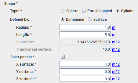
In this item, the user will define the shape. Only sphere, parallelepiped and cylinder are proposed. Note that the user has the possibility to enter either dimensions or surfaces. There is also the possibility to add solar panels by entering areas perpendicular to each vehicle axis: for example, X surface will correspond to the area perpendicular to the x axis.
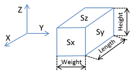
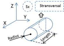
Note that, in the particular cases of parallelepiped or cylinder shapes, the distances or surfaces are defined as is:
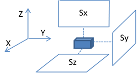
And for the solar panels:
Propulsive properties
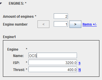
Propulsive properties will define the engines and the tanks existing in the vehicle (of course, by default, there is no engine and no tank). These definitions could have appeared in the maneuver sequence tab but it has been decided to keep them in the vehicle tab as it seemed more natural to group all vehicle data at the same place. For the engines, the user will have access to a list, each element of the list is composed of the name, the thrust level and the specific impulse.
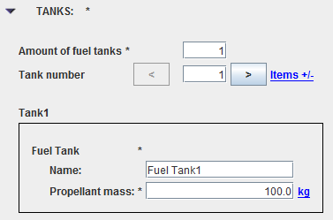
For the tanks, you will also get a list of tanks defined by a name and a propellant mass.
Note that the sum of propellant mass will be displayed as well as the total mass corresponding to the sum of the dry mass and all the propellant mass.
Aerodynamic properties
For most of the cases, the aerodynamic characteristics will only consist in constant drag and lift coefficient values.
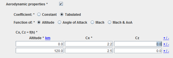
Moreover, if the vehicle shape is a sphere and there are no solar panels, it will possible to give more sophisticated aerodynamic coefficients as used for reentry trajectories, giving coefficients depending on altitude, angle of attack (AOA), Mach number or AOA & Mach number. An example of the XML structure corresponding to aerodynamic coefficients depending on altitude as used in the STELA S/W is available here (you just need to include it in a context file).
The aerodynamic forces will be computed as:
[math]F_{drag} = -\dfrac{1}{2}\ k\ S_{apparent}\ C_x\ V^2_{aero}\ \dfrac {\overrightarrow{V_{aero}}}{\|V_{aero}\|} [/math]
[math]F_{lift} = -\dfrac{1}{2}\ k\ S_{apparent}\ C_z\ V^2_{aero}\ \overrightarrow{u_{lift}} [/math]
... where:
- k is a multiplicative factor,
- [math]C_x[/math] is the drag coefficient
- [math]C_z[/math] is the lift coefficient
- [math]\overrightarrow{V_{aero}}[/math] is the spacecraft velocity wrt the atmosphere
- ρ is the atmosphere density
- [math]\overrightarrow{u_{lift}}[/math] is the unitary lift direction (perpendicular to [math]\overrightarrow{V_{aero}}[/math] and contained in the XZ vehicle plane)
- [math]S_{apparent}[/math] is the apparent total surface; the apparent surface is a function of the attitude law
- Sphere: the apparent surface is constant and no attitude law is required.
- Parallelepiped (and solar panels too): [math]S_{apparent} = S_x\ cos(α_x) + S_y\ cos(α_y) + S_x\ cos(α_z)[/math]
- Cylinder (sideslip angle is neglected): [math]S_{apparent} = S_x\ cos(α_x) + S_t\ sin(α_x)[/math]
- cos(α_x) = [math]\dfrac {\overrightarrow{V_{aero}}}{\|V_{aero}\|} \centerdot \vec X[/math] , being [math]\vec X[/math] the X satellite unitary axis direction and [math]\overrightarrow{V_{aero}}[/math] the s/c velocity wrt the atmosphere
- cos(α_y) = [math]\dfrac {\overrightarrow{V_{aero}}}{\|V_{aero}\|} \centerdot \vec Y[/math] , being [math]\vec Y[/math] the Y satellite unitary axis direction and [math]\overrightarrow{V_{aero}}[/math] the s/c velocity wrt the atmosphere
- cos(α_z) = [math]\dfrac {\overrightarrow{V_{aero}}}{\|V_{aero}\|} \centerdot \vec Z[/math] , being [math]\vec Z[/math] the Z satellite unitary axis direction and [math]\overrightarrow{V_{aero}}[/math] the s/c velocity wrt the atmosphere
Radiative properties
Radiative properties will consist in absorption, specular and radiative coefficients in the visible domain and eventually in the infrared domain. Note that a test of consistency is made in order to have the sum of the three coefficients equals to 1.
